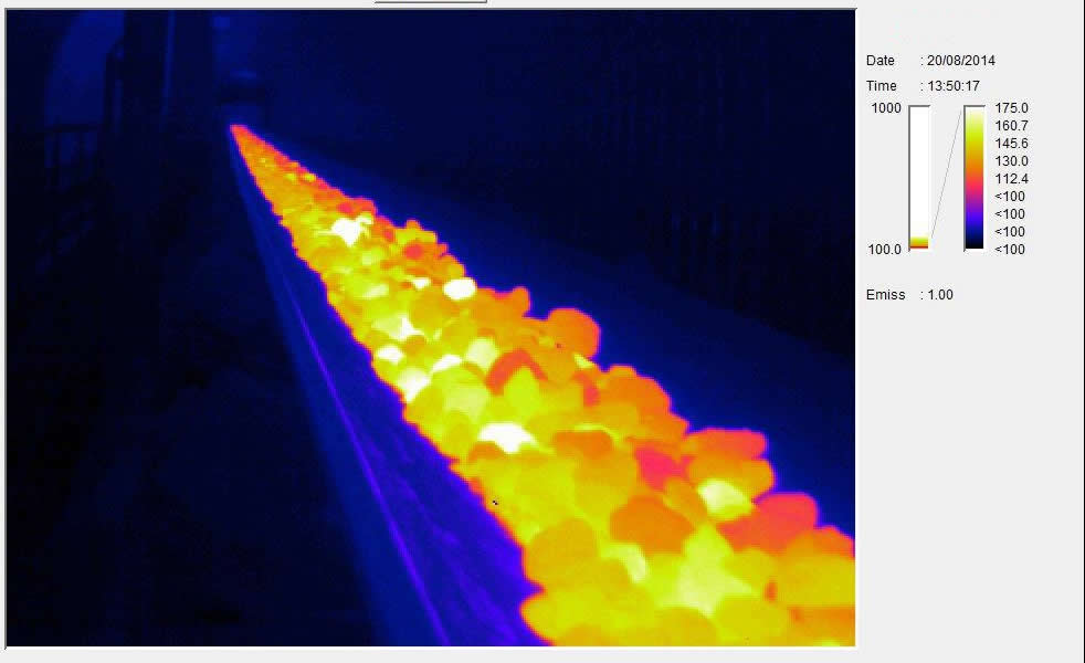
Infrared imaging diagnosis conveyor and crusher problems
Infrared imaging is useful for detecting thermal anomalies caused by mechanical problems in mines and plant equipment
Today’s companies are under great pressure to keep production at the same time lower costs. Infrared thermal imagers are valuable for measuring electrical problems, but some of the most important applications are mechanical systems. Plants usually contain thousands of low-speed bearings, and virtually impossible to use vibration monitoring to cost effectively check. For example, the conveyor system idler – has a direct impact on production when they fail – it is easy to check with thermal imaging. As a high degree of visual condition monitoring technology, infrared cameras are clearly and effectively present information. Before the equipment fails, you can identify and repair the source of hot anomalies, resulting in a variety of benefits:
Better predictive maintenance plans and overall maintenance and operating cost savings.
Reduce fire hazards in flammable environments.
More focused and more cost-effective maintenance.
May reduce the power required to drive the device.
A thorough IR investigation must include the effectiveness of all operating systems. This article will use the IR system for root cause failure analysis to demonstrate the need to pay attention to eliminating expensive maintenance problems in mine conveyors and crushers.
Temperature sensor comparison
In this case, a FLIR P60 with a 12 ° lens is selected for excellent thermal and visual image quality, spot size resolution, and temperature measurement accuracy, using an infrared camera for routine inspection of the ore crusher. The main purpose of the IR check is to determine the accuracy of the Pt100 (common platinum resistance thermometer) by comparing the countershaft and oil temperature readings to the camera’s LCD display and report any anomalies. This indicates that the placement of the sensor is critical to reporting the correct temperature, and the thermal imaging technique helps to determine the optimum area.
In order to clarify the anomalies expressed by the thermogram, the oil samples are drawn from the bottom of all reservoirs showing the temperature difference from the infrared image. The lowest suction point of the reservoir is located 100 mm from the bottom of the reservoir.
To ensure that the sample is removed from the bottom of the tank, a company specializing in oil filtration uses a check valve installed at the end of a 20 mm PVC electrical pipe to remove the bottom oil sample. When the PVC pipe is at the bottom of the reservoir, the valve plunger opens the valve and the oil flows inside the pipe. Remove the tube from the reservoir and drain the oil into the vial. And then the oil samples into the Xishan mine laboratory for analysis. The oil analysis report indicates that the oil pollution is very serious – actually polluting the filters in the laboratory equipment. The analysis shown in Table 1 shows that the bottom of the tank contains high concentrations of iron (Fe), copper (Cu), lead (Pb), silica (Si) and water (H2O). The infrared image actually shows the residue and accumulates at the bottom of the tank.
Then the problem is how to prevent the pump inhalation of water and sludge. One way is to raise the suction point above the sludge level, but this will not eliminate the sludge. The filter system of the reservoir can not effectively remove it and all the oil is drained from the tank because there is no drainage point, so any new oil will be contaminated when refilled. The diagnostic project presents four potential solutions:
Manual cleaning of the reservoir – manual cleaning can only be carried out in the main repair work of a specific crusher. To do this, the oil must drain, the tank opens, flushes out and cleanses. This method is effective, but very time consuming.
Use the filter system – to stir the oil in the reservoir to force the residue at the bottom of the tank to move. The oil will flow through the existing filtration system and be cleaned according to the filter specifications. It will take time and the filter is expensive. Some contaminants may pass through the filter, causing unnecessary wear.
Redesign the depot – redesign the reservoir so that sludge and water can be discharged at any time. The design can still protect the pump and filter, and does not need to drain all the oil, thus reducing costs.
Install a new filtration system on all reservoirs – one of which has a new filtration system that is kept cleaner than other oils, as confirmed by oil reports and infrared images. We can install the same filtration system on all other reservoirs.
Maintenance personnel choose C and D: Redesign the reservoir and install a new oil filter system on all reservoirs. It shows the results after eight months.
By periodically checking the reservoir, the infrared image will indicate the accumulation of residue at the bottom of the tank, and the maintenance personnel can remove the sludge.
Improve the selection of the appropriate conveyor parts